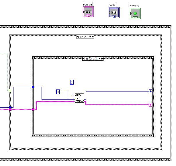
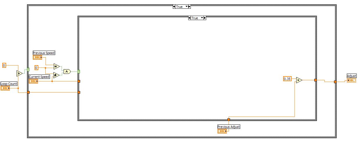
This
VI sets our adjustment when we start from a stop. This boolean
case is executed if our previous speed is zero and current is not equal
to zero.
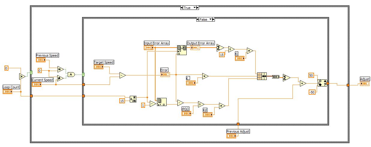
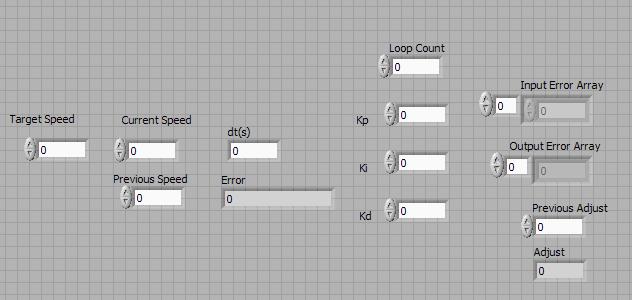
This
case applies a closed loop PID control loop to determine the adjustment
for the wheels based on the error from the feedback of the optical
encoders.
Turn VI:
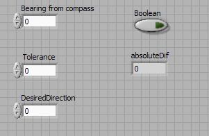
This VI turns the robot based on the desired direction, the current bearing and the tolerance.
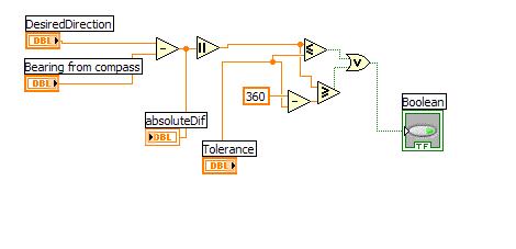
This
VI checks to see if the current bearing of the robot and the desired
bearing are within a tolerance. If the are it outputs a flag
saying so.
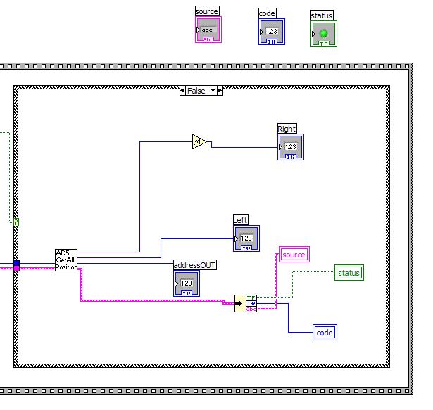
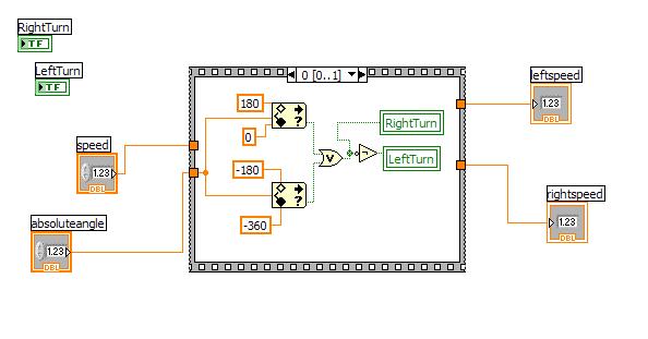
TurnSequence VI:
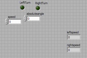
This VI executes a turning sequence setting the wheel speeds accordingly.
This brings in the absolute angle of the turn and the desired speed and determines if a right or left turn is being executed.
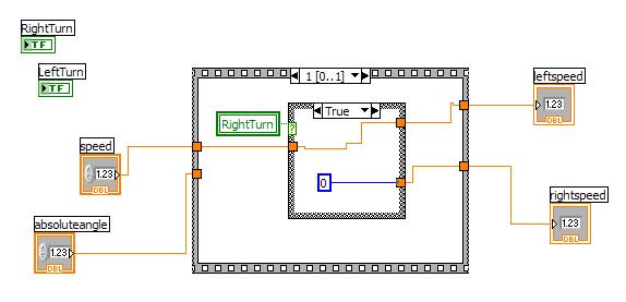
We
then execute the turn by sending the speed information to the outside
wheel. Int he case above we are making a right turn The
left turn would swithch the left and right wheel speeds.
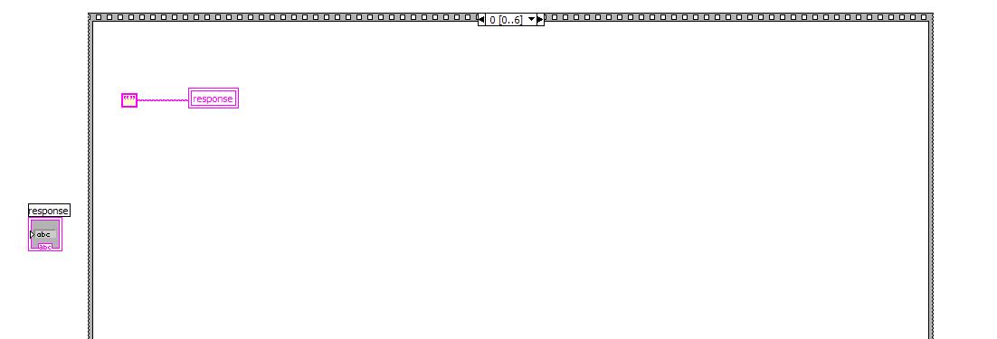
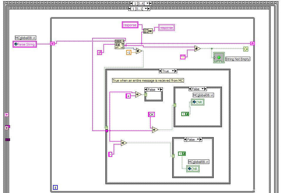
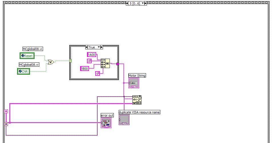
The Remote: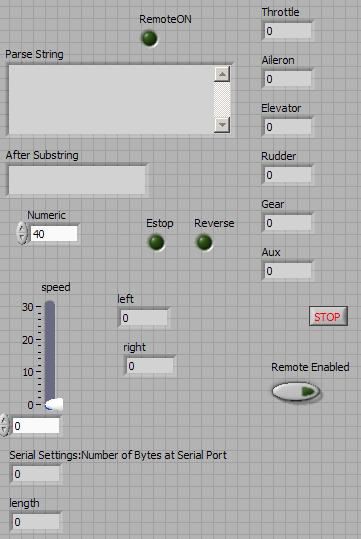
This VI takes care of conrolling the robot via the remote control.
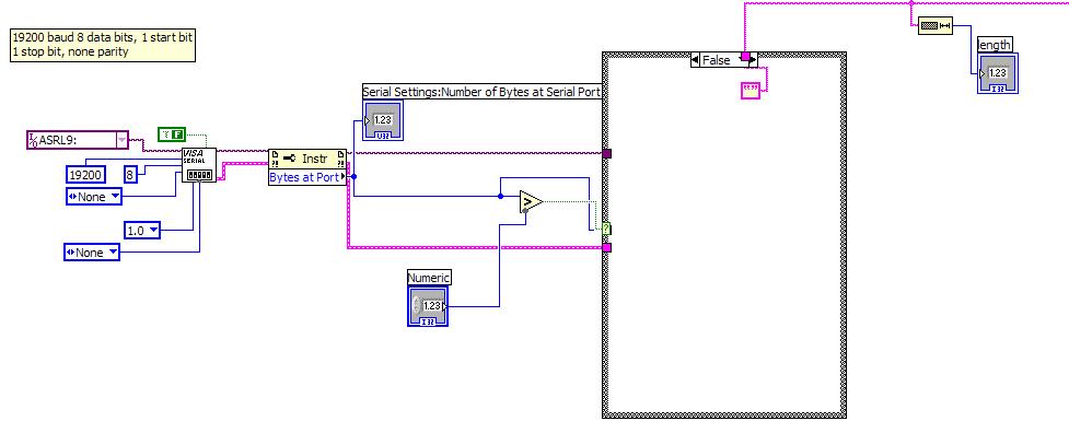
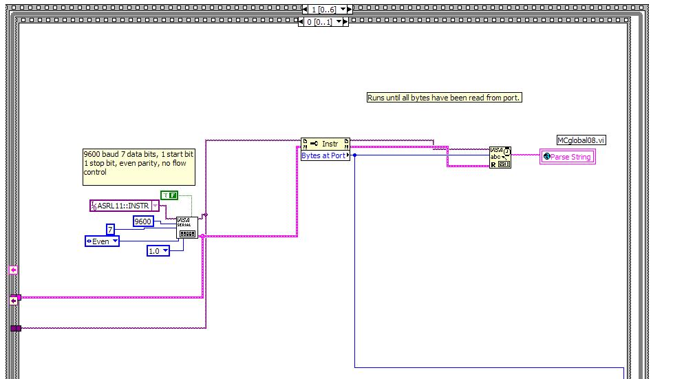
The first case of the structure sets up the serial connection of the remote control.
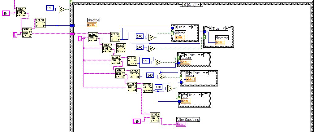
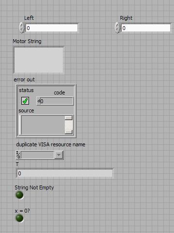
This case then parses the serial string into the double type variables that are represented in the string.
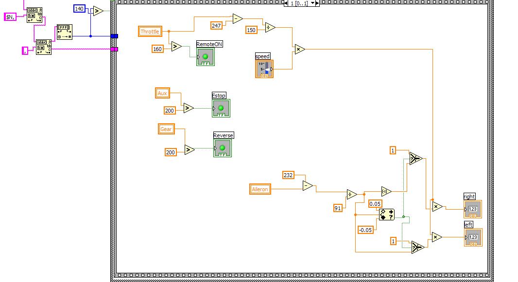
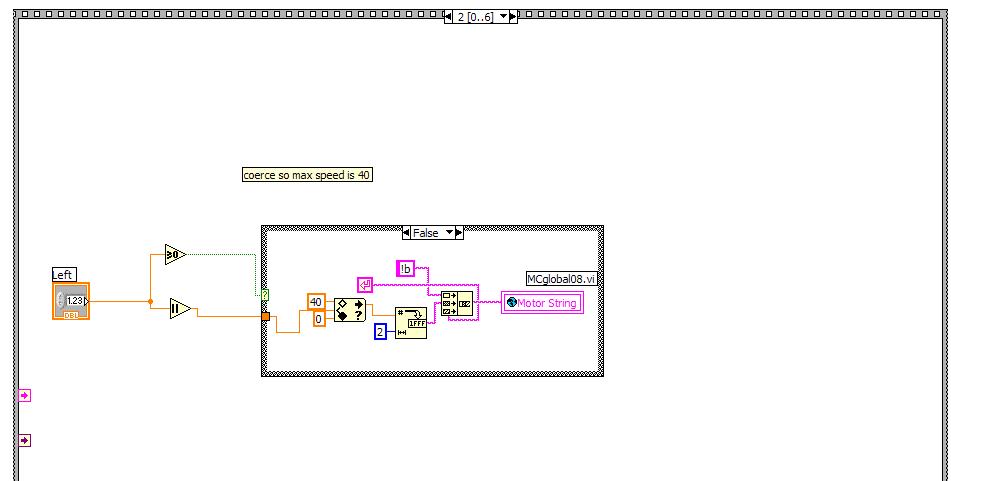
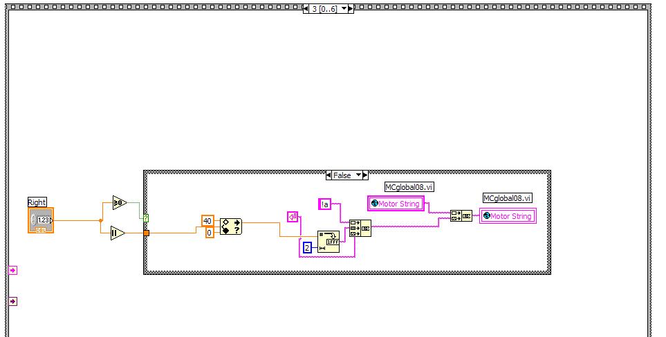
We then process the information we parsed out in order to control the robot. We generate left and right speeds.
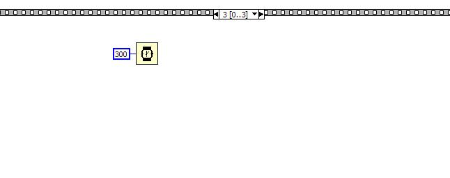
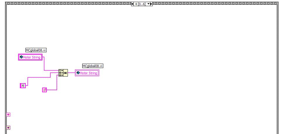
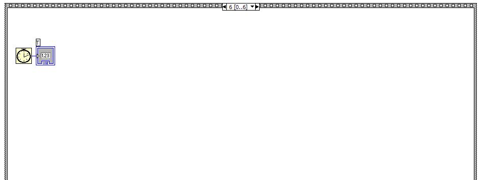
Finally in the last statement of the structure we set a 300 ms wait to allow execution.