News: Join the team! The Wunderbot V is looking for new memebers. Just contact someone on the contacts page!
Wunderbot - Vision Subsystem Tutorial
If there are any questions about this tutorial feel free to email me at patrickm@etown.edu and I will try to answer them.

The vision system consists of multiple VIs that function to bring in the processed image data from the Intellect Software.  The information is further
 processed to determine a target vector that is as close to parallel to both white lines as possible.
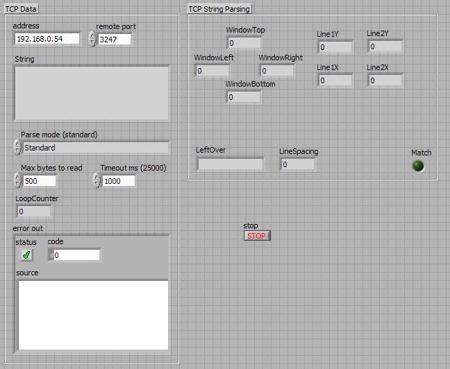
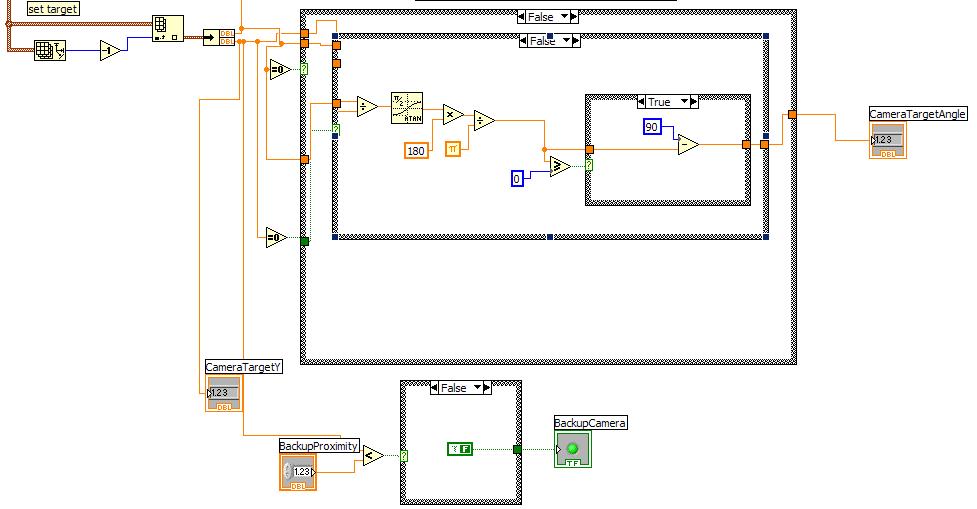
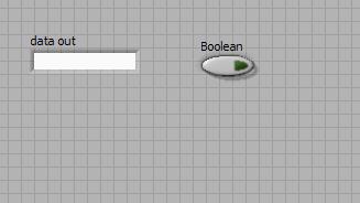
Vision_Main VI:


This is the front panel to the main Vision VI.  It displays the relavant vision information and allows for certains aspects of the process to be set, such as parse mode.


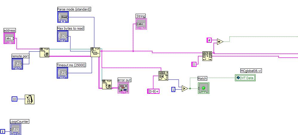
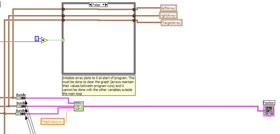
This shows the initialization of the camera input and the parsing of the data stream.   The data stream is then passed into the next frame shown below.


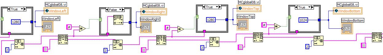
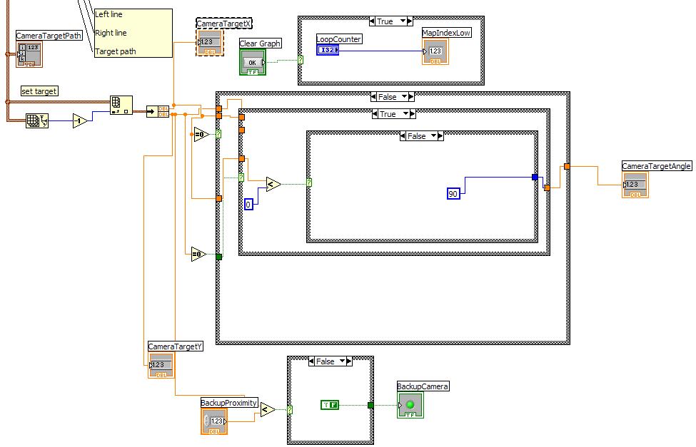
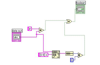
This section determines the window limit variables based on the decimal string data from the camera.  The setting is to a default value if the data is considered "bad" otherwise it is set ti the value specified in the data stream.


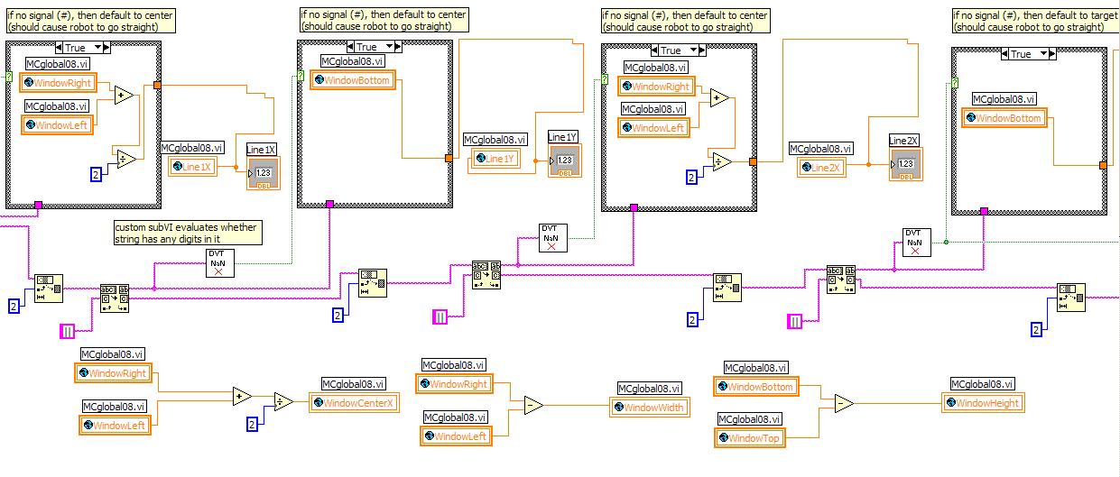
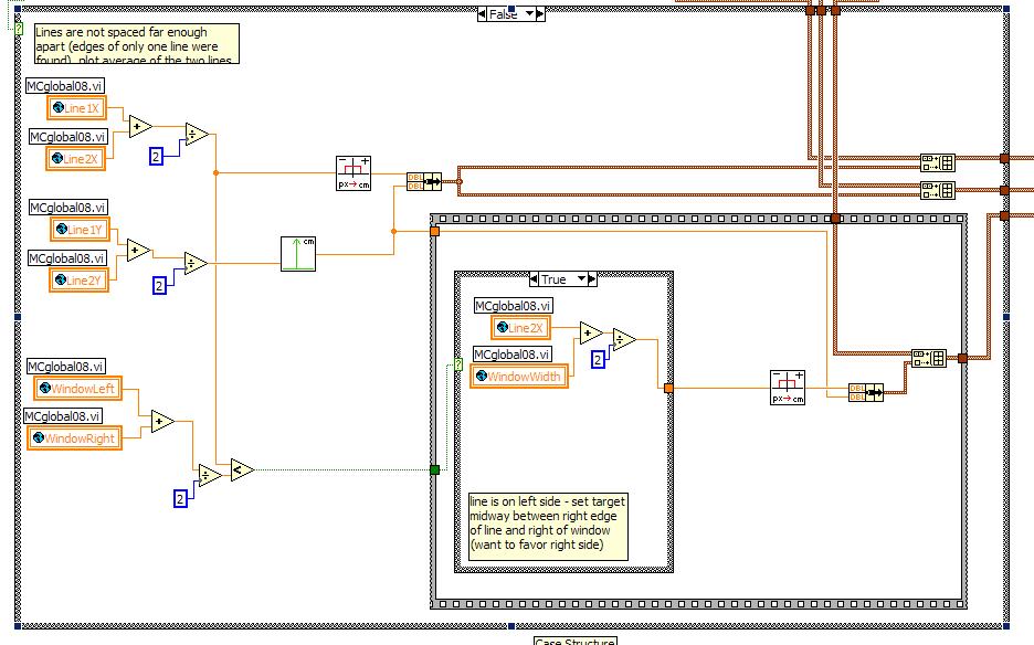
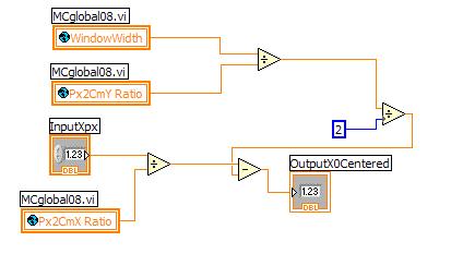
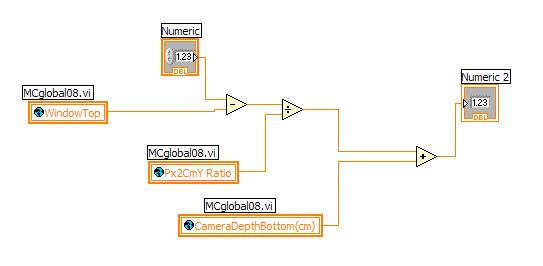
This section then sets the x and y limits of the lines.  It uses the window limits if the camera data is deemed incorrect.  Otherwise it uses the data from the camera.


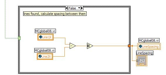
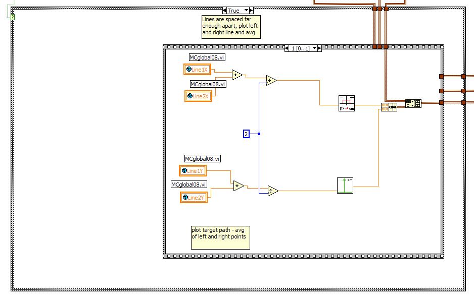
This calculates and sets the spacing between the lines based on the data from the lines found.
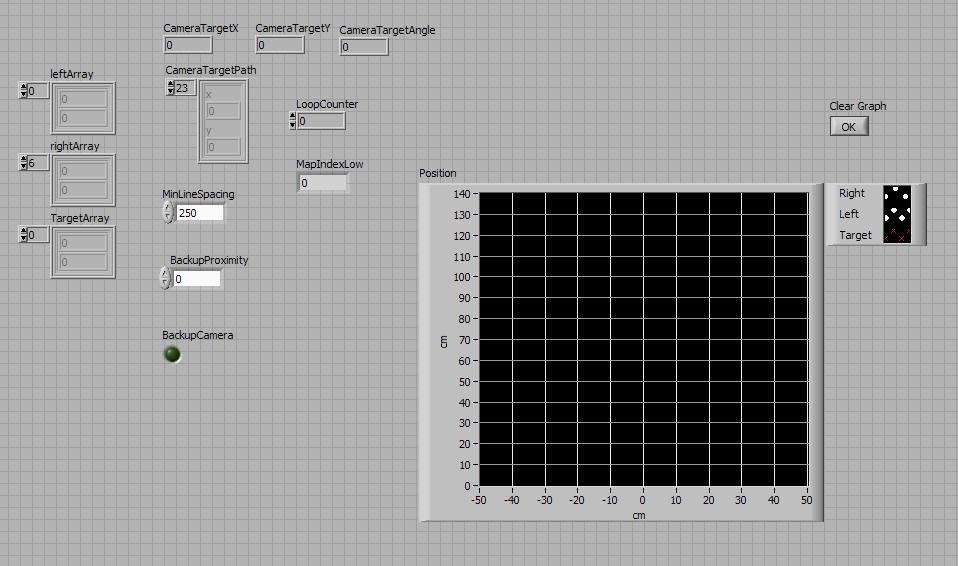
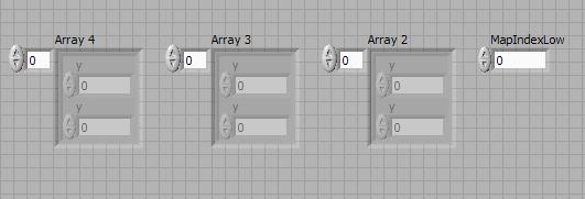
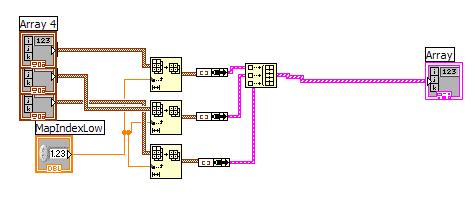
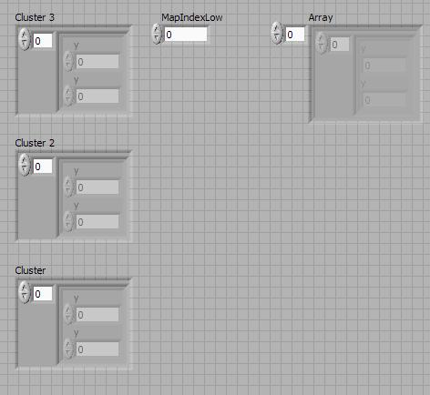
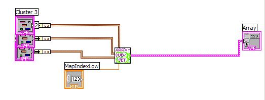
InputMapArray:


This is the front panel to another important subVI.  This sub vi generates the input map from the camera data.


This VI takes the parsed data from the main VI and from it determines the best vector to travel on.  In this frame we are preparing the data for the case where the lines were not spaced far enough apart.  In this case we determine our path based on the window limits and the line edge detected.


This is the opposite case from what is shown previously.  In this case we have detected two distinct lines and set our boundaries based on this.  


This then feeds up to a case selector to set the arrays up.  Each time the program is run this block initializes the arrays to zero is the loop count is equal to 1.  After this the arrays are fed straight through.


This section of the VI calculates the the target angle based on the inputs and the sign (to determine left of right).   The image below shows the second case of this section.


ArraySubset VI:


This is the front panel for the Array Subset VI.  This VI is used to organize the information into useable Arrays.


As seen in the block diagram the main function of the VI is to take the input arrays and formulate them into a single multidimentional array.

ArraySubsetFromBundle:


This is the front panel of another array subset vi .  This one condenses clusters/bundles of arrays.


As seen, thsi VI converts the clusters into arrays and feeds them into the previous ArraySubset VI.


ConvertXpxToX0Center:


This vi inputs the x value in pixels and outputs the centered X value to follow based on the input.


The VI takes the input and converts it by dividing by the Pixel to Cm ratio.  Then using the window width we can determine the output.


ConvertYpxToCm VI:


This vi converts the y input in pixels to cm.


Again we are dividing by a ratio to convert then adding an offset to determine the distance in centimeters.

DVT_NaN VI:


This VI determines if the string from the camera is a valid decimal number,  If it is we can use it, otherwise we ignore the data from that pass in the program.  The output is a boolean flag.=