and I will try to answer them.
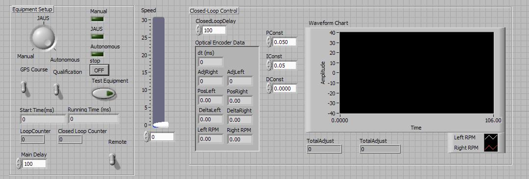
The Main
VI allows the user to set up the initial settings for the Wunderbot's
operation. There is a cirular switch to choose between JAUS,
Manual and Autonomous Mode. We have also included switches
to choose the GPS Course or Qualification/Obstacle Course in
Autonomous Mode or to use the Keyboard or Remote in Manual Mode.
The Speed Slider allows the user to select the speed in
manual mode. On the right hand side, the variables and output
of the PID controller are shown as well as a graph of the motor
response.
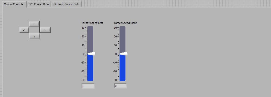
This is the manual control tab of the FrontPanel. This tab is
used when controlling the Wunderbot manually with either the keyboard
or the remote control. There are keys for the desired
direction of travel and slider indicators to show he target speed for
each drive wheel.
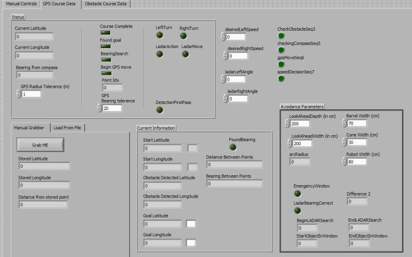
This is the GPS Tab showing the relevant information while navigating
the GPS course. There are various LEDs indicating bolean
variables and indicators showing current location. The
boolean LEDs are invaluable for debugging purposes allowing you to see
which variables are beeing set true and therefore which sequences are
being entered.
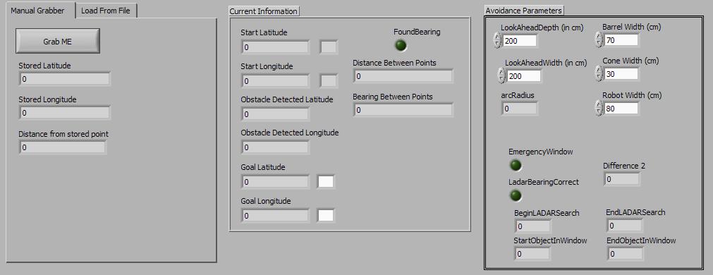
This is showing the manual grabber subtab of the GPS tab.
This manual grab allows the user to grab different GPS points
manually to set up a test GPS navigation course.
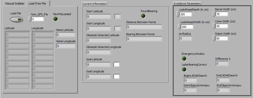
Thsis shows the from file subtab of the GPS tab. This allows
the user to load a file of predefined GPS points to navigate.
At competition the gps course is entered into the path
planning program and the ideal sequences is determined. This
sequence is then stored in a file and loaded to the Wunderbot for the
navigation course.
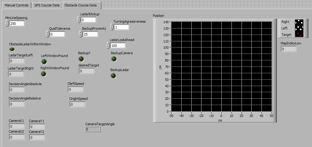
This is the Obstacle tab of the front panel. This allows the
user to set constants like turning aggressivness, lookahead distance,
backup proximity etc. It also displays pertinent information
from different decisions made in the code.
Variables - GLOBAL
All of the variables for the Wunderbot are Global so they can easily be
passed between different VIs in the control loop.
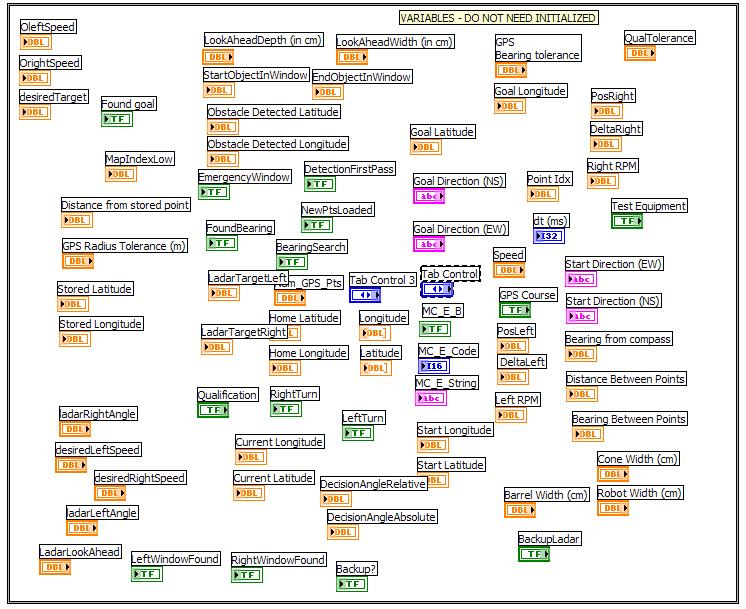
These are all the uninitilized variables used by he Wunderbot.
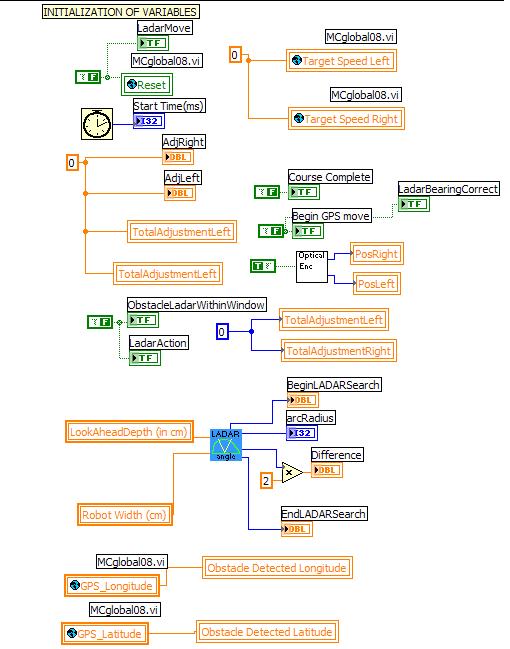
These are the initialized variables for the Wunderbot. As you
can see, this initializes some boolean variables to false and "primes
the pump" for some other systems to begin the control loop.
PID Controller - Closed
Loop Control
The Wunderbot used a PID (Proportional, Integral, Differential)
controller for closed loop control of the drive motors. This
allows the Wunderbot to compensate automatically for drive wheel
slipping or caster slipping.
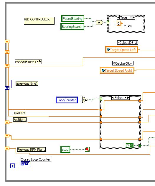
This shows the initialization and setup of the PID controller.
It is bringing in the current positions and incrementing the
closed loop counter. These values are then fed into a
sequence block that goes throught the steps of PID control.
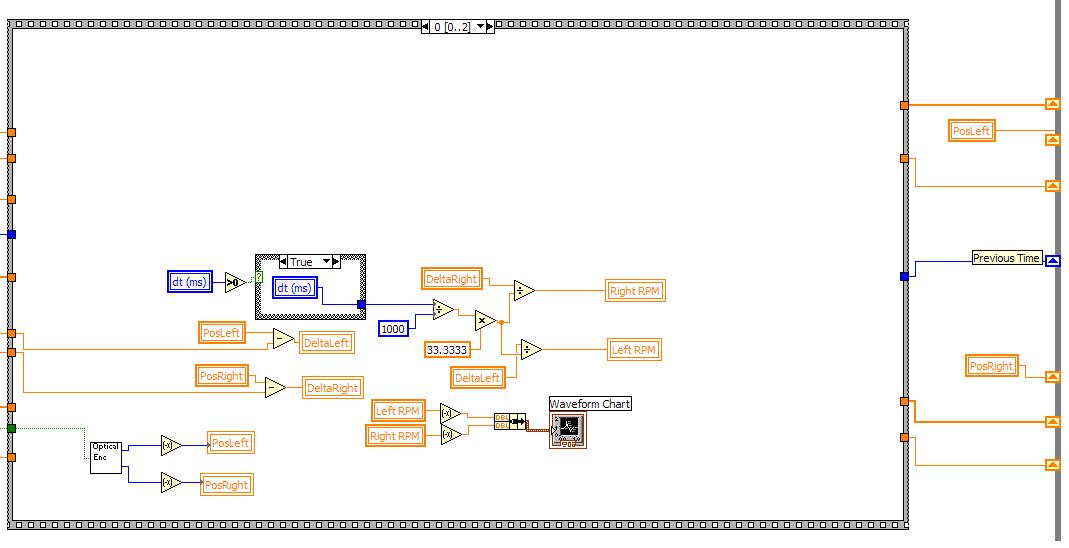
Many of the Wunderbot systems utilize sequences to simplify the overall
flow of the control algorithm. This shows the first case of
the PID controller sequence. This case takes the current and
previous positions to get a delta for use in the next case of the
sequence. It also determines the rpm of each wheel using math
logic blocks.
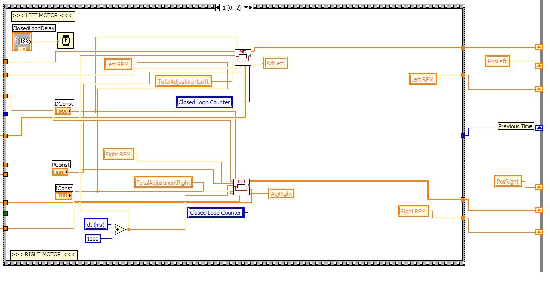
This case of the sequence feeds the PID constants into the PID subVI in
addition to the RPM and calculated adjustment for each wheel.
There is also a delay set to allow for the calcualtions using
current and previous positions. This feeds the output
positions through the sequence for use as feedback.
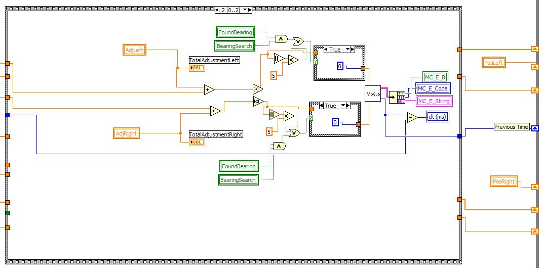
This case takes the adjustment for each wheel and applys it to the
current input for each wheel. This then does some
logic to determine if we have found a bearing or if the input to the
motor is less than 5. If either of these are true,
zeros are fed to the motor subVI. Otherwise, the adjusted
value is fed to the motor subVI.
The Main Loop
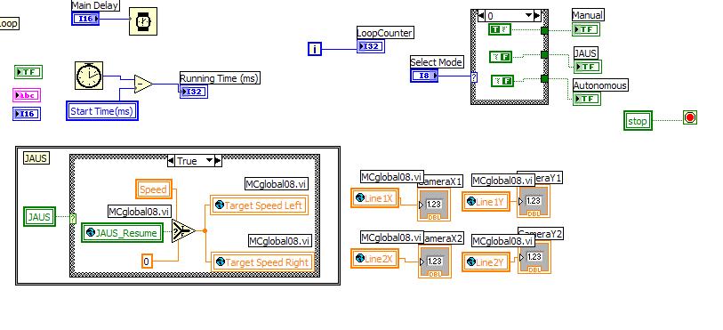
This shows the setup of the main loop
setting the delay, calculating runtime and selecting modes.
Also this shows the JAUS setup, If JAUS is selected the JAUS
case is executed.
Manual Control
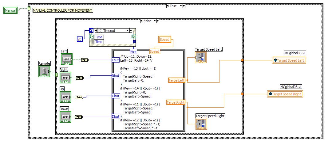
This is the Manual Control Case with the remote switch off.
This maps the up, down, left, and right keys to set target
speeds for the desired directions.
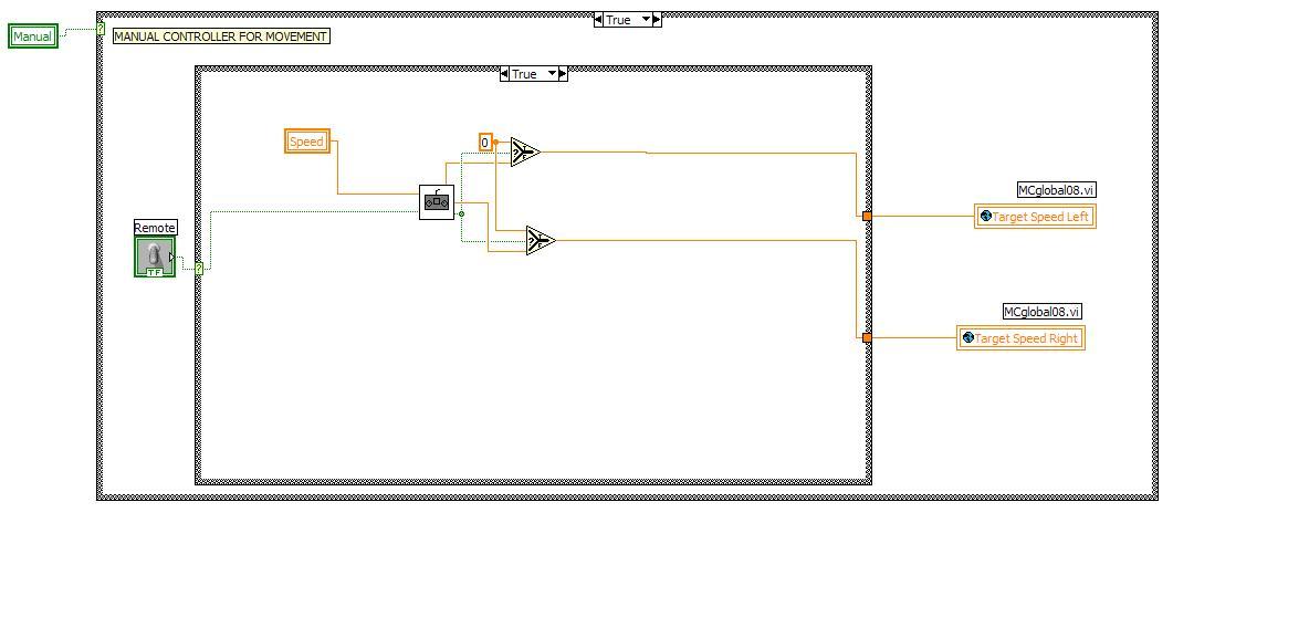
This is the manual control VI using the remote control. This
feeds the set speed into the remote control subVI which outputs the
target speeds for the left and right wheels. There is also a
coded emergency stop as well. If the estop is on then the
logic forces a desired speed of zero to stop the robot.
GPS Navigation

This shows the basic flow diagram for the GPS Navigation course.
This is quite similar to the obstacle course that will be
discussed below, except that the GPS takes the GPS bearing into account
while the obstacle course sequence checks the LADAR and Vision and
makes a decsison based on both sets of data.
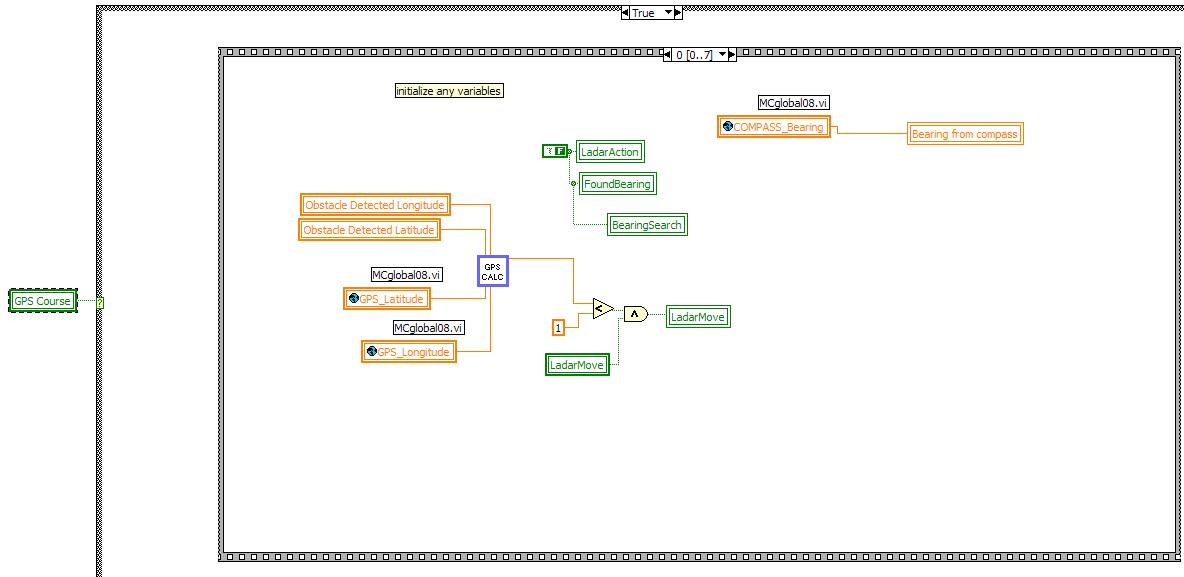
This sequence case initializes any variables using the GPSCalc subVI
as well as initializes some boolean variables to false.
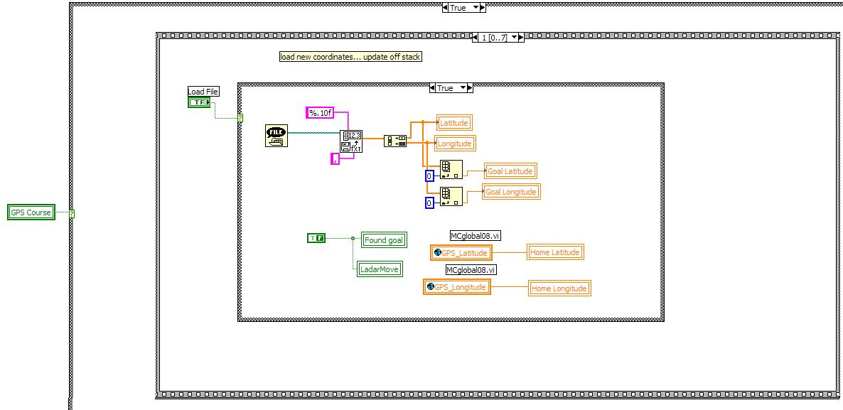
This second case checks to see if the load file boolean variable is
true. If it is, it loads the next GPS point. If not it checks
to see if we have found our goal, if we haven't, it continues through
the loop.
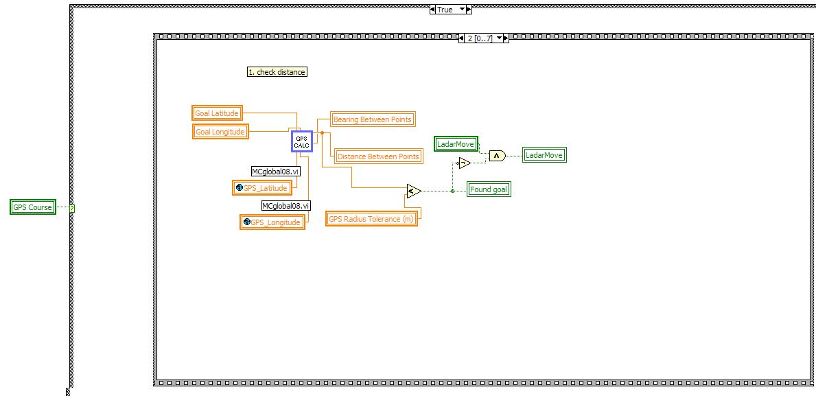
The third case of the sequence checks the distance to the next goal GPS
point, It then determines if we are witthin the expected
radius of the GPS point. If so we set FoundGoal to true. It
then does logic to determine whether or not to make a LadarMove.
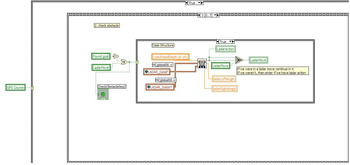
In the fourth case we check if we have found the goal or are in a
LadarMove - If either is true we execute the block and check
the Ladar Window. This checks this outputs if an obstace is
in the window. If it is, we execute a Ladar Action.
If we have a Ladar Action or if we were in a Ladar Move, we
continue the Ladar Move.
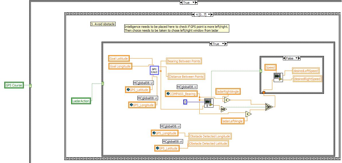
The fifth case execute when we have a Ladar Action. This case
determines the position of the obstacle and determines whether the
robot should turn left or right to avoid it. If there is a
larger window left of the obstacle we turn left. If there is
a larger window right we turn right.
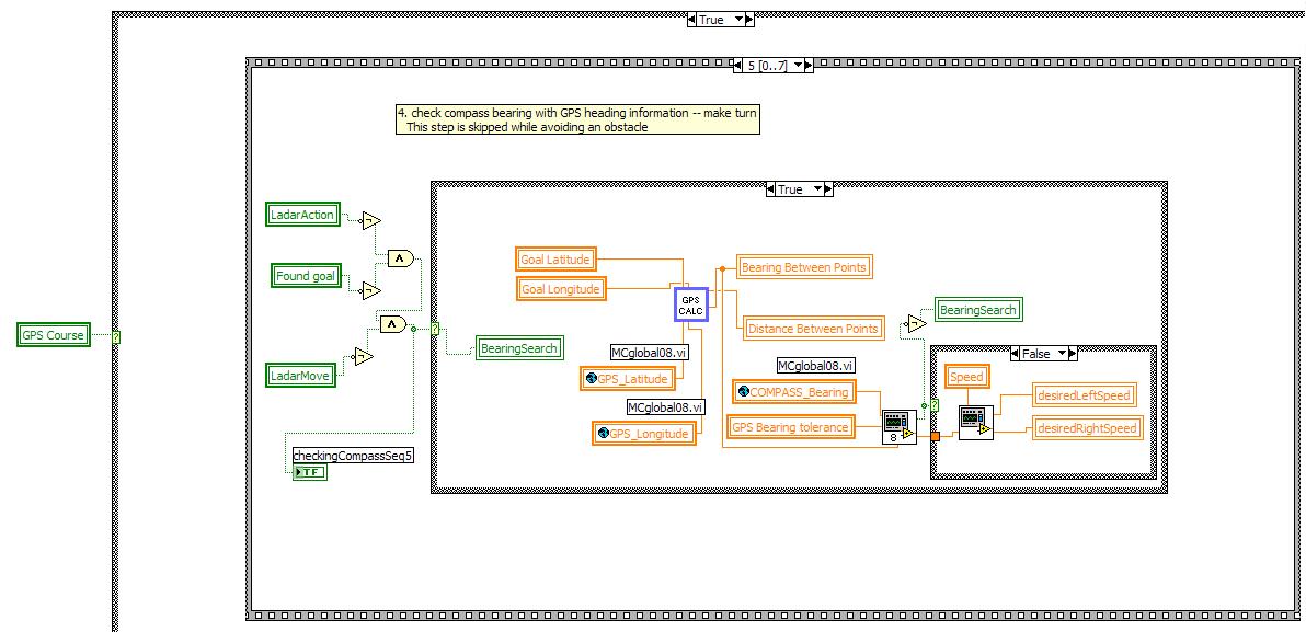
The sixth case is only entered if we do not have a Ladar Move or Ladar
Action.. In this case we determine if we are on the correct bearing by
checking the current compass bearing against the desired bearing to the
next GPS point. We then turn toward the desired bearing if
necessary.

The sixth case executes a GPS move. This means that if there
are no obstacles in the way and we are on bearing move straight.
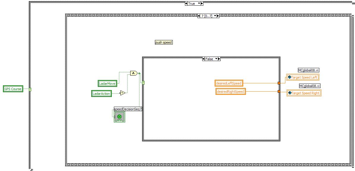
This final case pushes the speeds to the wheels.
Obstace Course
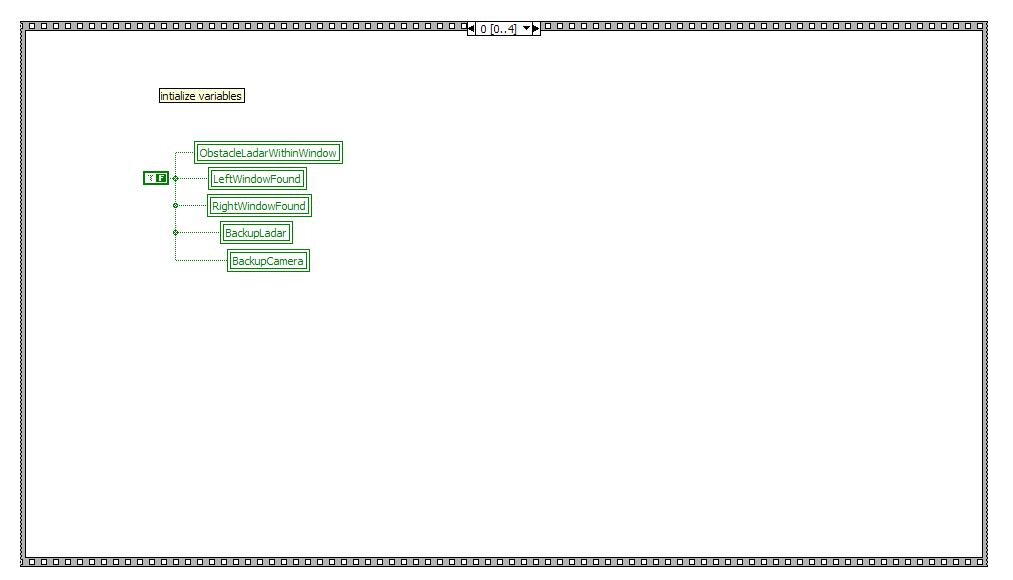
The first case of the obstacle course initializes all the boolan
variables to false.
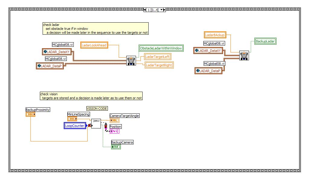
The second case checks the ladar and the vision simultaneously.
It sets if there is an obstacle in the ladar view and ckecks
whether or not we need to backup based on ladar or vision.
Finally it also detemines the target angle based on the
vision system output.
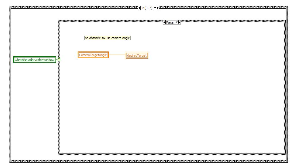
Thie third case has a great deal of parallel cases. The first
shown here detemines if there is an obstacle in the window.
If there isn't then we used the camera target angle.
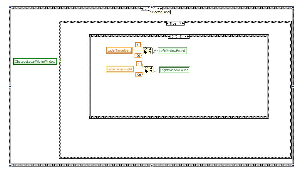
If there is an obstace in the window then we need to go through another
sequence statement. The first step of this sequence sets
windows based on the ladar target. The window tells us if
there is a space past the object on each respective side.
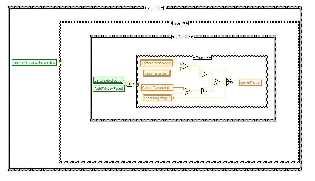
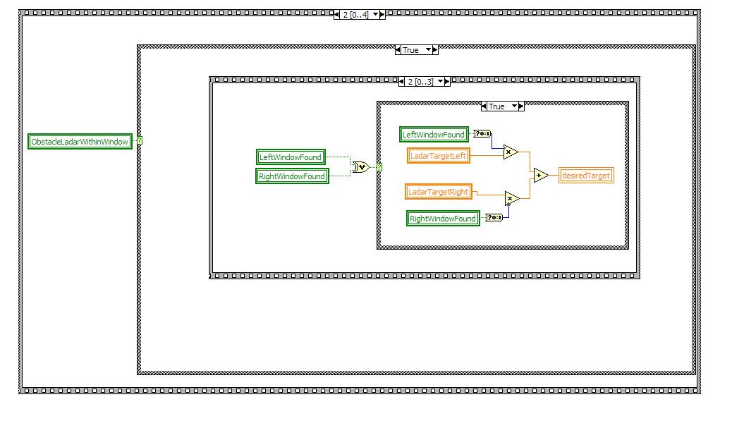
In this case it we execute if we have an available window on both the
left and right sides of the obstacle. In this case we use the
ladar target that corresponds most with the camera target,
This ensure that we will be moveing away from both lines and
objects if possible.
The third sub case takes the XOR of the left and right window boolean
variables. This means if we have one but not the other we
move toward the open window ignoring the camera target.
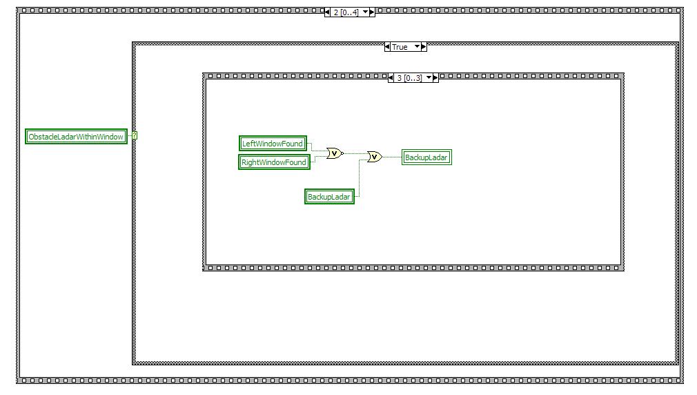
This final case says that if we do not have a window on either side
then we need to back up and look for a window again.
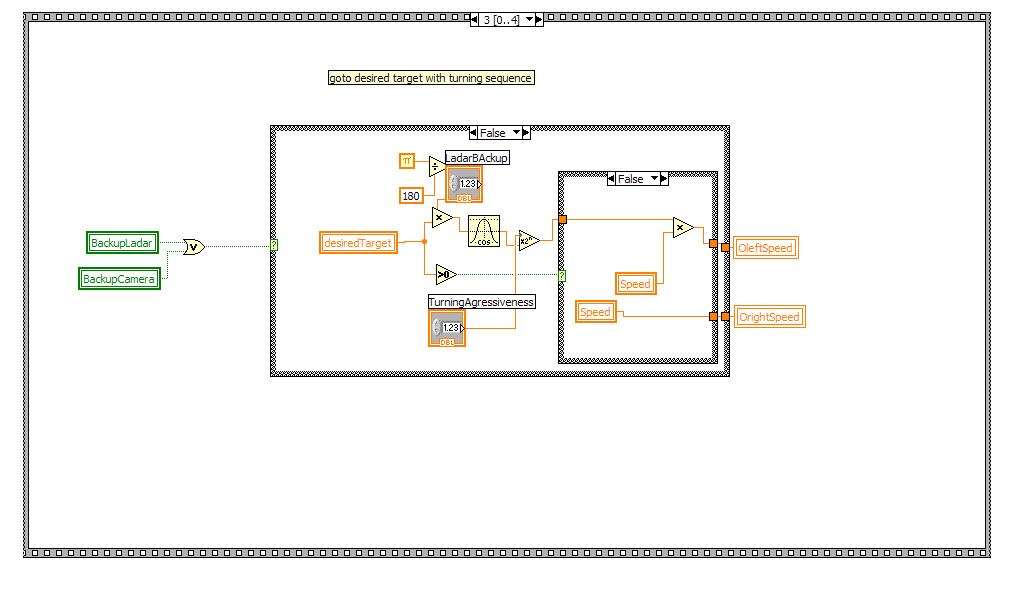
We then continue in the main sequence statement. we check if
we set either the Camera or Ladar Backup variables. If we
didn't then we turn based on the determined desired target from the
previous case. The turn is based on turning aggressivenes and
the desired target,
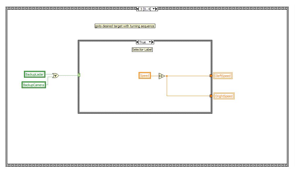
This is the case if we did return that we need to back up. In
this case we negate the speed in order to back up.
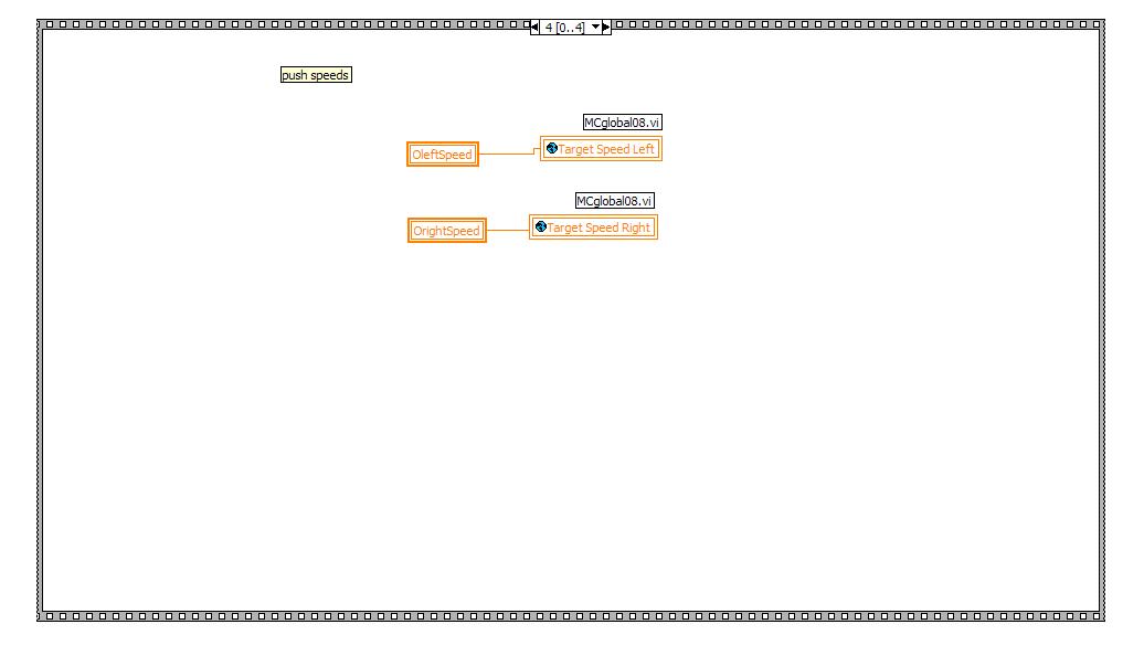
Finally, when we get to the final case of the sequence we push the
speeds to the motor.